
End-to-End Embedded Product Development: From Concept to Production
 Wrirten by
Manaam Rehan
Wrirten by
Manaam Rehan
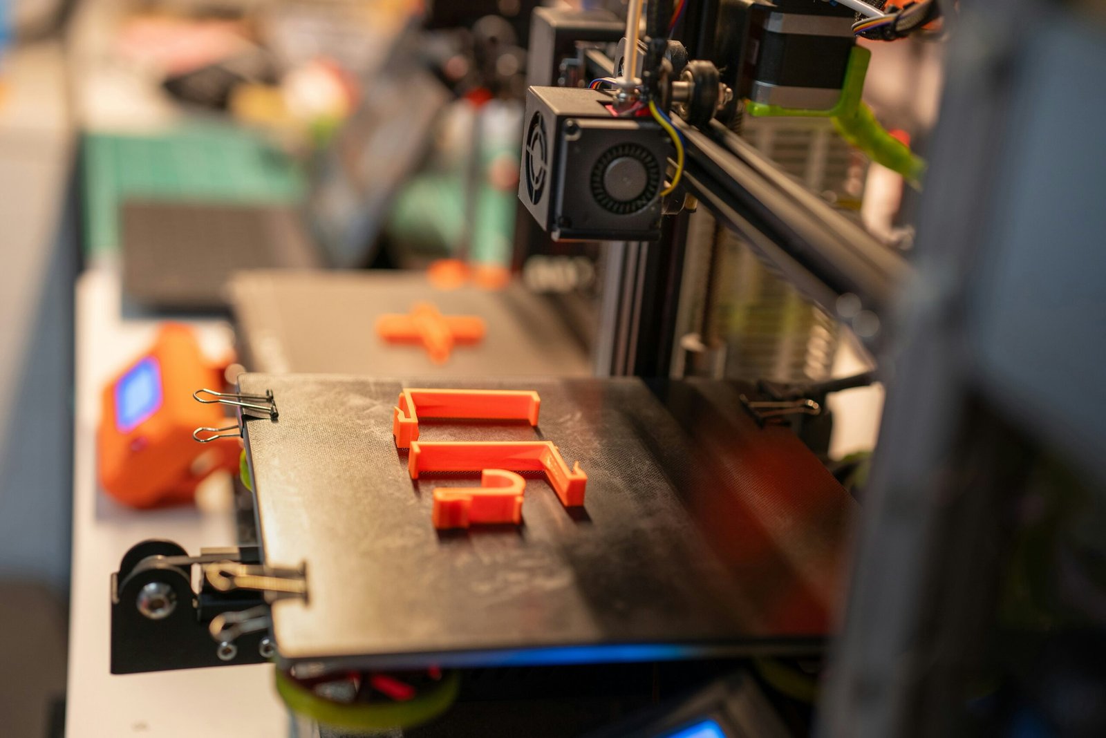
Bringing a complex embedded system or IoT device to market is a multi-layered journey that requires a perfect harmony between hardware engineering, industrial design, firmware development, and cloud integration. Developing a smart product in disconnected silos often causes severe design bottlenecks, signal bugs, and expensive manufacturing re-spins.
Navigating this lifecycle successfully demands an integrated, step-by-step methodology. Partnering with an expert hardware design company ensures your product moves smoothly from an initial concept sketch to a high-yielding factory production run. Here is an execution blueprint for the complete embedded development cycle.
Before drafting schematic lines or coding low-level drivers, you must build a comprehensive physical and strategic baseline for your product.
Compiling the Product Requirement Document (PRD): Every successful project begins by translating a business concept into an explicit technical blueprint. The PRD outlines your target retail unit cost (BOM), battery lifespan goals, operating temperatures, and exact wireless protocols. Locking down these parameters early shields your project from scope creep and keeps development budgets stable.
Shaping the Enclosure via Industrial Product Design: Once the boundaries are clear, industrial designers model the device’s external aesthetics, ergonomics, and physical size. This phase carefully balances beautiful styling with real-world mechanical requirements, ensuring internal real estate is optimized for component mounting, battery cavities, and assembly screw bosses.
Executing Strategic Product Design Services: True innovation means designing for assembly limitations from day one. Engineering teams focus on draft angles and uniform wall thicknesses during early enclosure design. This proactive focus ensures your custom outer casing can be affordable and reliably produced using high-pressure factory plastic injection molding tools.
.
With your external boundaries established, the engineering team shifts focus to creating the custom physical electronics that act as your product’s brain.
Developing Schematics and Selecting Components: Electrical architects translate your system requirements into a functioning block diagram, picking microcontrollers, sensors, and power chips. Comprehensive product design services map out how these chips communicate via high-speed digital paths, protecting fragile silicon nodes from overvoltage spikes or thermal overloading.
Routing the Multi-Layer Printed Circuit Board: Layout engineers place components strategically to minimize signal lengths and ensure optimal power delivery. Utilizing specialized pcb design services for iot devices, they isolate noisy digital high-speed lines from sensitive analog sensor inputs, ensuring data packets transfer without corruption across the board stackup.
Implementing Wireless IoT Hardware Design Services: Connected products demand expert RF trace routing to maximize antenna efficiency and range. Engineers use dedicated tuning networks to match track impedance, ensuring your Wi-Fi, Bluetooth, or cellular transceivers transmit data cleanly without consuming excessive battery power or dropping cloud connections.
The development cycle reaches an interactive milestone when digital schematics are fabricated into functional physical hardware samples.
Deploying Engineering Firmware Development Services: A freshly manufactured prototype board remains completely inert until low-level software instructions are flashed onto its internal registers. Code architects build hardware abstraction layers, verify sensor drivers initialize perfectly, and optimize sleep cycles to ensure your software drivers perform reliably.
Executing Professional Board Bring-Up and Debugging: Initial prototype runs are subjected to systematic laboratory testing before full software development begins. Utilizing specialized hardware debugging services, engineers apply current-limited bench supplies, probe clock signals with high-bandwidth oscilloscopes, and eliminate unexpected power drops or signal distortions.
Assembling Works-Like and Looks-Like Prototyping Solutions: Combining the custom circuit boards with rapid 3D-printed or CNC-milled enclosures yields an integrated prototype. Having these early physical units allows your software and mechanical departments to run field validation trials simultaneously, cutting weeks off your total time-to-market.
The final phase of your embedded development journey involves transferring your verified design assets over to a commercial manufacturing plant.
Running Comprehensive Design for Manufacturing (DFM) Reviews: Before cutting steel factory tooling molds, engineers audit all design files against factory limitations. They check pick-and-place alignment clearances and component orientation markers, which updates production blueprints and maximizes factory assembly line yield.
Integrating Custom Test Fixtures and Bed-of-Nails Jigs: Mass assembly lines require instantaneous quality checkpoints. Engineers place dedicated copper test points across the board layout to interface with automated “bed-of-nails” factory testers, allowing automated machines to verify electrical safety and flash final firmware onto production units in seconds.
Clearing Global Regulatory Compliance Audits: To legally sell your connected device, it must pass rigid global testing parameters like FCC and CE. Designing your grounding layouts and EMI filtering with a premier product design consultancy ensures your architecture clears radio emission and safety audits smoothly on your very first laboratory attempt.

Q: What is the biggest hidden risk when managing an embedded product development lifecycle?
A: The biggest risk is a lack of alignment between separate hardware and software contractors. If code developers are not in communication with the board layout team, hidden errors during board bring-up lead to intense finger-pointing, expensive redesigns, and missed market windows.
Q: Why should startups invest in a custom circuit design over a pre-made development board?
A: Off-the-shelf boards are physically bulky, power-hungry, and filled with extra components that inflate your retail unit costs. Custom engineering allows you to shrink your product’s footprint, extend field battery life, and maximize long-term profit margins.
Q: How can we accurately predict and manage component obsolescence issues during mass scale?
A: Professional design teams proactively scrub your Bill of Materials (BOM) during development. They substitute single-source parts with globally active alternatives and build secondary drop-in component footprints directly onto the PCB layout to shield your factory from unexpected supply shortages.
Navigating an end-to-end embedded product development process requires a disciplined, multi-disciplinary approach that connects industrial styling, electrical layouts, low-level firmware coding, and production logistics. By executing your product timeline in structured phases—from detailed PRD mapping to rigorous board debugging and automated factory validation—you protect your enterprise from catastrophic manufacturing failures and product recalls. Spending the time to thoroughly validate every engineering milestone upfront builds a stable commercial technology platform. If you are ready to move your connected concept away from speculative sketches and turn it into a high-yield, market-ready physical asset, contact our engineering team today to receive a complete technical and production roadmap.